Defining the required cooling capacity is often the first step in specifying a chiller, but what is cooling capacity?
Cooling capacity can be described as the measure of a cooling system’s ability to remove heat. Cooling capacity is calculated under standard conditions, taking into account the volume of process fluids being cooled, and ambient temperatures.
Load vs Cooling Capacity
Load can be defined as the among of energy the chiller is required to remove from the system. The load must be greater than or equal to the process’s heat generation, otherwise the chiller is only able to remove a portion of the energy. This results in heat being left within process fluids, which will eventually lead to increased process fluid temperatures due to accumulation of energy within the system. High process fluid temperatures can affect operation and cause shut down. This is known as under-sizing.
Factors Affecting Cooling Capacity
Cooling capacity figures provided by most manufacturers are generally calculated based on 20ºC water delivery temperature, and 20ºC ambient temperature.
Ambient air and facility water changes:
- In order for a chiller to effectively process the heat load, the temperature difference between the hot refrigerant gas and the ambient air or facility water must be sufficient. As the temperature of ambient air increases, the condenser’s ability to transfer the process heat from the refrigerant to the ambient air or water is reduced. This results in higher condensing pressures and a potential reduction in performance. To be able to size a chiller accurately, it is important to know the maximum ambient temperature or water temperature. With this information, it is possible to select a chiller with enough cooling capacity to meet the needs of the application.
Set temperature changes:
- If the difference in incoming temperatures between the liquid refrigerant and returning process fluids are reduced, there will be a decrease in the evaporator’s performance. This is common where chillers are set to run at low temperatures.
- If the chiller supply temperature is lower, the temperature of returning process fluids will be lower as there is less temperature differential to drive heat transfer. As the set temperature decreases, so does the performance of the chiller. Performance will increase as the set temperature increases, up to the maximum temperature within the designed temperature ranges.
Process fluid changes:
- Most manufacturers calculate cooling capacity using water as the heat transfer fluid. Use of another heat transfer fluid, such as glycol or oil, could result in a lower cooling capacity. This is because other fluids have a lower specific heat, lower density, and lower thermal conductivity than water.
- Some manufacturers use ethanol, which has a higher specific heat capacity, for these calculations. Information regarding process fluids will be detailed within the manufacturer's specifications.
Flow rates and temperature differentials:
- As the mass flow rate within a system increases, the temperature difference decreases. Where flow rate is low, the volume of water flowing through a pipe section is lower, allowing water molecules to be heated faster. Where flow rate is high, there are more molecules of water within a pipe section per second, meaning that it takes longer to heat them up.
Chiller operation and maintenance:
- Dust and debris on the fans and fins of air-cooled condensers can restrict airflow, reducing the cooling capacity of the chiller. Routine maintenance and cleaning can help to prevent this. If the environment is particularly and unavoidably dusty, it is possible to oversize a chiller.
- Fouling can occur within water-cooled condensers due to scale formation, corrosion, and biological growth due to poor quality water. This forms a layer on the walls of pipes, impeding efficient heat transfer between the refrigerant and heat transfer fluid, decreasing the efficiency of the chiller. Use of clean water with added corrosion inhibitors can help to minimise the risk of fouling.
Oversizing a chiller
Oversizing occurs where cooling capacity is greater than load. Although there are situations where overcooling is recommended, there are risks. Oversizing comes with a risk of overcooling, where process fluid temperatures are driven below the desired set point. This can negatively affect the operation of the chiller and cause shut down. It is more difficult to maintain a stable temperature when oversizing because the refrigeration system tends to overshoot the target temperature.
Cooling Capacity Controls
To prevent overcooling when oversizing a chiller, cooling capacity controls are required. Cooling capacity can be controlled in a number of ways:
Compressor cycling:
- This is a basic method of controlling cooling capacity. Within a chiller, the compressor drives the refrigeration cycle, providing the system with cooling. This compressor is either on or off, running at 100% whenever on. By cycling the compressor, you are able to stop cooling within the chiller.
- However, compressor cycling can cause damage to the compressor, or reduce it’s life expectancy. Most compressors feature an anti-cycle delay, only allowing 12 starts per hour in order to protect the compressor from damage. The compressor must wait for a minimum of 5 minutes prior to restarting, meaning that temperature stability can suffer. An oversized chiller will cool too much, triggering the compressor to cycle off. Whilst the compressor is off, there is nothing to remove energy from the heat transfer fluid. This allows energy within the system to build, resulting in an increase in temperature. When the anti-cycle timer is active, the temperature of heat transfer fluids may continue to increase, overshooting the set point. This creates a wave pattern of overcooling, followed by overheating.
Hot Gas Bypass (HGBP):
- By modifying the refrigeration circuit and bypassing hot gas directly to the evaporator, an additional heat load is created. This prevents the chiller from overcooling and needing to turn off the compressor. Addition of a Hot Gas Bypass avoids compressor cycling, and any resulting temperature instability.
- However, the addition of a Hot Gas Bypass can waste significant energy.
Combination of HGPB and Compressor Cycling:
- Larger capacity chillers may use a combination of HGBP and compressor cycling, as multiple compressors may be used to meet the full specified capacity. Use of multiple compressors provides stages of unloading, improving the chillers ability to match the load in steps. This helps to avoid large temperature fluctuations and anti-cycle timers. The Hot Gas Bypass helps to ensure temperature stability at the last stage, or compressor, wasting a fraction of the energy.
Variable speed design:
- A controller will constantly monitor the heat load and adjust the compressor speed using a variable frequency drive. This allows for peak efficiency and temperature control, whilst eliminating the need for a Hot Gas Bypass. The chiller will only work as hard as is necessary to provide optimum performance with reduced energy consumption.
Digital scroll compressors:
- These are used within systems with only one or two compressors and make it possible to actively adjust capacity and save energy. Compressors operate in two states – loaded and unloaded. When in a loaded state, the compressor operates at full capacity. In an unloaded state, there is no compression or capacity. By separating the scrolls in the compressor, it is possible for the compressor to move from loaded, to unloaded, and back. This modulates the capacity of the chiller. When unloaded, the compressor remains on, but consumes less energy. This helps to avoid cycling issues.
Cooling Capacity Units
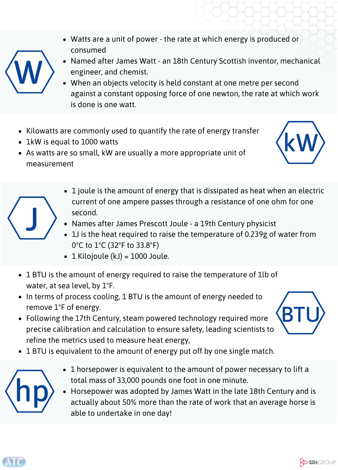
Click here to download our useful conversion chart.